|
|
Welcome to - Lew's Model Boats - and more! |
go to Home Page |
| LewsModelBoats.org is not a commercial web site. Lew is a scale model builder/hobbiest (model boats and more). Views on this web site are opinions of the author and not driven by any commercial entity. Opinions are welcome - by mailing Lew (see contacts). © Copyright 2024 Lew's Model Boats. Disclosure: This Lews Model Boats do not have any financial ties to any company, political affiliation nor any other subsidy and has no gains from these and any other person(s). Lews Model Boats and this site is purely for the enjoyment of its viewers and others who enjoy this hobby. |
U.S.S. Monitor - Positive Floatation
With a significant amount of the U.S.S. Monitor model being underwater there is much concern as to if there was a leak, "would the model sink?" Most models have a high freeboard, the distance the side of the hull is above the water line. The Monitor had 14-inches freeboard fully loaded. At 54mm scale, that means only 7/16-inch.
To prevent a catastrophic event such as the model sinking if "swamped" or a leak by accident or a bad seal, two things need to be looked at: Improving the seal or creating positive flotation.
Positive flotation is achieved when the boat weigh less than the water it displaces. The safest method is to fill voids with flotation material (such as insulation foam available at build and home centers). This should be done to the point that if all remaining cavities for the equipment such as the motor, remote control, battery, and turret mechanism were totally flooded, the model would still float.
Calculating the space needed for Equipment
The easiest way is to calculate the volume of the upper hull
above the water line. As the sides of the upper hull are vertical,
one can calculate the surface area multiplied by the desired draft.
The surface area is determined by the outer perimeter of the upper
hull minus the approximately 4-1/2 foot diameter of the anchor well
and the approximately 2-1/2 foot by 9 foot upper cavity for the
propeller. (The lower part of the propeller cavity is well below
the water line, so it does not enter into the calculations.) so,
here are the calculations:
| Table 1 | Original | 54mm scale model | Comments |
| Surface area: | 5,780.7 sq ft | 605.39 sq in | |
| Volume above waterline: | 6,644.1 cu ft (@14-inches) | 264.86 (@7/16-inch) | |
| Each additional unit more: | 481.7 cu ft (per each 1 inch) | 18.92 cu in (per each 1/32-inch) | |
| Density of water: | 64 lbs per cu ft (salt) | .036 lbs per cu in (fresh) |
About the
Waterline
The original Monitor's waterline was 14 inches (mode:
7/16-inch) fully loaded. Keep in mind that as consumables (chiefly
coal, and to some extent ammunition) were used, the hull lifted up.
So, a model "riding high" (some of the below waterline showing)
would not be out of the ordinary, and the modeler could use this to
their advantage to gain more interior space yet still maintain
positive buoyancy. The above calculations will help determine how
much.
Working the Numbers
In Table 1 we saw the numbers for the hull and the density
of water. The original ship held about 80 tons of coal in it's
bunkers. When coal is burned, the remaining ash is about 5% of the
weight. To round off numbers, we will look at segments of about a
little over 10 tons of coal being burned (accounting for the ash).
In Table 2 we can se how the 10 ton segments effect the ship and the
equivalent weight effect the model for neutral buoyancy. Keep in
mind that all equipment and ballast would displace water in event of
hold flooding.
| Table 2 | Original | 54mm scale model | Comments |
| Weight of water displaced above W/L: | 103.81 tons | 21.79 pounds | |
| Weight of water per unit increase: | 15.41 tons (per each 1 inch) | .68 pounds (per each 1/32-inch) |
Setting the Model's Cruising Waterline
In simple term, if about 15-1/ tons of coal (less
than 1/5 of capacity) were spent, the ship would ride 1-inch
higher (the model would ride 1/32-inch higher. For each
1/32-inch height, the model would weigh .68 pounds less and gain
an additional 18.92 cubic inches of neutral buoyancy.
Sealing the Hull
As mentioned earlier, the
most significant problem with modeling this ship is dealing with
the low freeboard. Problem
areas include
 any
deck openings such as the flush smoke ports (when the portable
stacks are not used), around the turret. There are several
options as to sealing the radio gear, turret drive, smoke
generator, and propulsion system, yet still have access to the
inside of the hull for maintenance, replacements, and repairs.
any
deck openings such as the flush smoke ports (when the portable
stacks are not used), around the turret. There are several
options as to sealing the radio gear, turret drive, smoke
generator, and propulsion system, yet still have access to the
inside of the hull for maintenance, replacements, and repairs.
The most common method is to have part of the deck removable, most likely in several sections, where the seams in the removable hatches matching the seams in the deck's armor plates. These removable sections then could either be water-tight or allow access to more secure water-tight hatches directly under them.
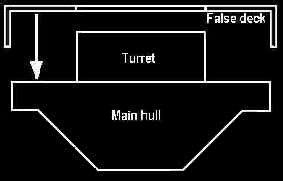
Another idea that has been explored is the entire deck and armor belt is removable (diagram at the right). That deck covers a second hull that has multiple sealed hatches. This is an interesting approach as it leaves the main deck in one piece and provides a lot of access to the inside of the main hull, depending on the builder's needs.
any
deck openings such as the flush smoke ports (when the portable
stacks are not used), around the turret. There are several
options as to sealing the radio gear, turret drive, smoke
generator, and propulsion system, yet still have access to the
inside of the hull for maintenance, replacements, and repairs.The most common method is to have part of the deck removable, most likely in several sections, where the seams in the removable hatches matching the seams in the deck's armor plates. These removable sections then could either be water-tight or allow access to more secure water-tight hatches directly under them.
Another idea that has been explored is the entire deck and armor belt is removable (diagram at the right). That deck covers a second hull that has multiple sealed hatches. This is an interesting approach as it leaves the main deck in one piece and provides a lot of access to the inside of the main hull, depending on the builder's needs.